Tag Archives: cae

Introduction to Engineering Simulations (CAE)

(This article giving an overview of the field of Computer Aided Engineering has been written for PuneTech on our request by Dr. Ajey Walavalkar, regional manager of services and support at Ansys Fluent India, a company specializing in CAE and CFD applications and services, which has a development center in Pune. See the end of this article for more about Ajey.)

In the earlier PuneTech article “An Overview of CAD,” Yogesh and Amit have provided a very good overview of the CAD technology spectrum. There, we learnt where and how “Analysis” and “Simulations” fit in the overall scheme of CAD. This article is intended to provide a broad overview of the area called Engineering Simulations, which spans across the above mentioned “Analysis” and “Simulations” fields on the CAD canvas.

What are Engineering Simulations?

The analysis of vibrations and the dynamical behaviour due to excitation forces have been applied routinely to cable-stayed bridges using SMR devised analysis tools. Note that similar techniques have been used to analyse the resonance behaviour of large floating bridge structures.

The example shows an eigenmode of a large cable-stayed bridge (model and analysis with B2000 by The Dutch National Aerospace Research Institute (NLR)). The figure displays a vibration mode, the shape being artificially amplified to emphasize the deformation. Source http://www.smr.ch/services/csm

Let’s say you want to build a bridge. Not just any bridge, but a massive suspension bridge to rival the Golden Gate Bridge in San Francisco Bay Area. How do you decide the type of steel, the span length, the tower height, the thickness of the cables, the depth of the foundations, and other design parameters? You will wonder that if this problem was solved in the 1930s then why is it tough today? The simple answer is, ‘Solved? Yes! But at what cost and effort?’ Previously, the simple solution for most tough engineering problems was to ‘over-engineer’ the solution by building in a ‘huge factor of safety’. Today, this design process is lot more accurate and efficient. Today, the engineering team will start off by considering the effects of vehicles (weights and speeds) plying on the bridge, the wind forces that will sway the bridge, the waves that will hit the foundation, the steady long-term corrosive effects of weather, etc. These effects can studied by mathematically modeling these factors and ‘simulating’ them with a help of a computer. Such ‘simulations’ greatly help today’s engineers to come up with the exact design that is safe and that saves time and costs.

Wikipedia defines Simulation as follows:

Simulation is the imitation of some real thing, state of affairs, or process. The act of simulating something generally entails representing certain key characteristics or behaviors of a selected physical or abstract system.

Engineering simulations are simulations applied to engineering problems. These can range from simple “back of the envelope” calculations to full fledged systems simulations using High Performance Computing.
Mathematical modeling and physical modeling are two main aspects of engineering simulations. Mathematical modeling refers to the description of a particular phenomenon in terms of mathematical equations. E.g. If you wish to find out the distance a canon ball will travel when fired from a canon at certain angle, at a certain speed; you can write some mathematical expressions and solve them to calculate this distance. This is mathematical modeling. Now suppose you are firing that canon ball at a mountain cliff and the ball is going to bounce off and roll down the slopes of the mountain, how do you find out where that ball will end up? Here you need to also consider the physical structures and that leads you to physical modeling.

Uses of Engineering Simulations

Today, computer aided engineering simulations are used extensively in designing and development of almost all industrial products. In addition to product designing, simulations find their uses in troubleshooting of existing systems and research & development of new processes. Many times the field of computer aided engineering simulations is also termed as Computer Aided Engineering (CAE). There are numerous software products available in the market and they offer variety of engineering simulation capabilities. Many organizations also use their in-house built simulation software products that capture their time proven design practices.

There are many objectives in performing engineering simulations:

  1. During product design cycle, engineering simulations enable the designers to evaluate various design options without getting into costly prototyping and testing. Use of simulations in the design process can help narrow the design choices to very small set that can be taken to the prototyping and testing phases. Even with physical testing, one can inspect and measure only a small number of variables at few select locations. Whereas simulations can provide visual information on all the variables of interest at all locations inside the simulated space.
  2. Simulations can help troubleshoot deviation of actual performance of system/product from the desired one.
  3. Simulations can help designers and analysts to evaluate response from the product or system, to ‘highly-off’ design conditions, e.g. evaluating the safety of a nuclear reactor facility in hurricane conditions etc.

What is involved in performing engineering simulations?
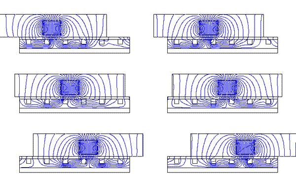
Animation of electromagnetic simulation showing development of magnetic flux lines.

Animation of Electromagnetic Simulation showing development of magnetic flux lines. Source http://www.ansys.com/solutions/electromagnetics.asp

The domain of engineering simulations is mainly divided based on the physics that is captured in the simulation. Based on this criterion, the domain is broadly categorized as follows

  1. Structural analysis Simulations
  2. Thermal & Fluids Simulations or Computational Fluid Dynamics (CFD) simulations
  3. Electronic Design Automation

In any type of engineering simulation, there are three main stages.

  1. Pre-processing: This involves determining the region in space that one will need to use in simulation. This region, (with all the necessary geometry details that are needed to attain the goals of the simulation) is then drafted on a computer using various CAD software tools. This space domain is then discretized into various small volumes or elements called computational cells. This is called meshing or gridding of the domain. Depending on the physics involved, the extent of the physical domain, the accuracy desired and the computational resources that are available, this mesh or grid can range from a few hundred cells to few hundred million cells. Ansys recently broke the Billion cell barrier.
  2. Solving the governing equations: This step involves solving the governing mathematical equations that describe the physics that one desires to capture at all the computational cells. Finite Element Method (FEM), Finite Volume Method (FVM) and Finite Difference Method (FDM) are the most commonly used numerical techniques that enable solving the governing partial differential equations on discretized domain on computers. To perform these calculations, many inputs need to be provided. The results achieved from the simulations are directly dependent on the inputs provided. Techniques of parallel computing enable use of multiple cpus on a network to be used for solving a single simulation. In this technique, if you have a mesh with say 2 million cells, and have a network cluster of 8 cpus, each CPU can solve equations for 0.25 million cells and thus the simulation time can be reduced significantly as compared to a single CPU solving equations for all 2 million cells.
  3. Post-processing: This stage involves understanding and analyzing the results of the simulations. The simulation software tools provide a mix of visual as well as alpha-numeric reporting of various variable of interest to the user so that the user can derive the information from the simulation needed to fulfill their objectives.

Most of the engineering simulation software tools provide connectivity to variety of CAD drafting packages so that geometries can be imported in from various different sources. Many of them provide ability to customize the solvers such that users can add their own/ proprietary physics/knowledge in the simulations. The post-processing allows results to be ported to various other analysis tools including optimization tools. Through these customizations, many users of these software tools have embedded the engineering simulation technology deep into their design process. Of the software tools available in the market, many are general tools that can be used by any industry vertical where as there are few tools that are developed for only one or few industry verticals and are easier to use to simulate applications in that particular industry.

Future of engineering simulations

Animation of FLUENT CFD simulation of flow over an elite male swimmer in the glide position. Source: http://www.fluent.com/news/pr/pr69.htm.

At present, most of the software tools available in the market are solving various physics involved in the real life process or equipment separately. However, in reality all these physics occur simultaneously and affect one another. The world of engineering simulations is moving rapidly towards incorporating multiple physics and their interactions to provide more reliable predictions. The engineering product development community is exploring, what is known as “Simulation Driven Product Development”, so that full benefits of engineering simulation technology can be leveraged to their competitive advantage. Some of the major software providers in this space have already started offering multi-physics solvers that enable organizations to march in this direction.

Another new facet that is coming in focus now is of knowledge management. Use of these simulation software tools, is generating a lot of engineering knowledge which the companies would like to leverage in their future design processes. With this need in mind, integrated engineering knowledge management platforms that will work seamlessly with the engineering simulation tools are being developed.

Engineering Simulations scene in Pune

Pune has attracted most of the main players in this exciting domain.

Ansys Inc, one of the leading companies in developing the engineering simulation software tools is present in Pune. Ansys has development, testing, sales, support and services functions for India based as well as worldwide customers being conducted out of the Pune office. Ansys develops structural analysis, CFD, EAD as well as optimization tools that are used widely in almost all industry segments.

In addition to Ansys, companies such as Siemens PLM, MSC Software, Abaqus also have presence in Pune.

Pune also has a growing list of companies that are using these engineering simulation softwares. Companies such as Cummins, John Deere, Dow Chemicals, Eaton Corp, Honeywell, etc have set up their product development centers in Pune which use these tools. Tata Motors, Tata Technologies, research wing of TCS, TRDDC and Tata’s new venture in HPC, CRL are also exploring the field of engineering simulations actively. Additionally engineering services consultants such as Tridiagonal, Pacific Mindware are also based in Pune.

Education institutes such as COEP too are now well equipped and have elective courses that allow students exposure to this interesting field.

About the author – Dr. Ajey Walavalkar

Ajey has over 10 years of experience in the Computational Fluid Dynamics industry. Currently, he is a Regional Support and Services Manager for Ansys Fluent India, in Pune. He has experience in successfully simulating various applications across industry domains, building teams of engineers for delivering CFD projects, support and services in an offshore setting. Ajey has a Ph.D. in Mechanical Engineering from Pennsylvania State University, USA, and a B.E. in Mechanical Engineering from COEP.

Reblog this post [with Zemanta]

An overview of Computer Aided Design (CAD)

Pune is a hotbed of activity for CAD Software – both, for users as well as developers. We asked Yogesh Kulkarni, who has more than a decade of experience in this industry to team up with Amit Paranjape to give PuneTech readers an overview of this area.

What is CAD?

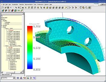
Nonlinear statistics analysis of a 3D structure subjected to plastic deformations. Image by Joël Cugnoni courtesy the Wikimedia Project

CAD is defined as the use of computer technology to aid in the design of a part, a sub-assembly, or an entire product. Design can include Technical Drawings with Symbol based Representations, Visualization, 3D Rendering, and Simulation. Note, the term ‘Product’ could range from a small Widget, to an iPOD, too a large Building. Components of CAD technologies have also found widespread use in somewhat unrelated fields such Animation & Gaming.

Consider a World-War II era vintage B-17 Flying Fortress bomber; probably the only bomber ever to manufactured on an assembly line. How was it designed? Each and every part was painstakingly drawn on a drafting board. The various components and sub-assemblies were represented through various engineering drawing conventions. Yet the true visualization of how all these complex pieces fit and worked together, was left to that of the top engineers’ minds. And what about the complex 3-D shapes such as the wings? How were they designed and tested? Actual wooden models had to be created for this to visualize their shapes and test out their air-flow characteristics in wind tunnels. You can think of an army of literally hundreds of Draftsmen working on various pieces of this complex machine. Cars were designed the same way. ‘Machine Designing’ had elements of ‘Art’ in it. This style of designing was with us until recently. It’s only in the past 2-3 decades (even more recent in many SMEs in India) that computers have started replacing these ubiquitous ‘A1’ sized drawing boards that ruled the designers shop for so many decades.

Fast forward to today, and now let’s look at how Boeing’s latest 787 Dreamliner is being designed. This truly 21st century aircraft is built with composites instead of the traditional aluminum structures, and a whole bunch of other interesting innovations. All put together, Boeing claims to improve fuel efficiency by over 20% compared to other modern day commercial airplanes. All the designs of the Dreamliner are done using CAD. From the smallest widget to the entire airframe, the drawing, designing, assembling, and visualization is done on computer monitors. These designs are also evaluated for their validity and performance via Computer Aided Engineering (CAE). CAE works in conjunction with CAD to simulate and analyze various mechanical and other aspects of the design. Similarly, Computer Aided Manufacturing (CAM) works closely with CAD to help manufacture the complex parts on Computer Numerically Controlled (CNC) machines.

History

CAD has evolved a great deal over the past few decades along with the rise in computing and graphics power. Earlier CAD solutions were simple 2-Dimensional solutions for drawing machines and structures. These still represented a big step forward over drawing boards in terms of ability to save, edit and reuse drawings. Initial 3-Dimensional solutions were based on ‘wireframe models’ and ‘surface modeling’. Loosely speaking, these represented the outer edges and the external surfaces of a solid object in mathematical terms. Real 3-D capability involves representing the real object as a solid model. Mathematically, this involves a series of complex equations and data points. This had to wait for computing power to catch-up. Only in the late 1980s did this power become available to a wider engineering community via desktop workstations.

At a high level, you can think of a CAD package to have 2 important pieces: 1) The backend mathematical engine and 2) The front-end graphical rendering service.

Earlier CAD programs were primarily written in FORTRAN. Present day, CAD packages are typically developed in C or C++. Rendering was not a strong point of the earlier solutions. However over the past 2 decades, life-like rendering and simulation (rotation, motion, etc.) have become a reality. This capability has also taken this technology into the Animation & Gaming fields.

Associated Areas

CAD works closely with other allied areas such as CAE (Computer Aided Engineering), CAM (Computer Aided Manufacturing), as well as PLM (Product Lifecycle Management). In fact, CAD/CAM or CAD/CAE are often used together to describe the entire workflow. In this section we will take a brief look at these allied areas. In future, PuneTech will feature more detailed and specific articles about each of these areas.

Computer Aided Engineering is the use of computer technology to support engineering tasks such as analysis, simulation and optimization. These tasks are often performed by the engineer in close synchronization of the actual CAD activities. An example of ‘Analysis’ could be leveraging mathematical techniques such as ‘FEA/FEM’ (Finite-Element-Analysis/Finite-Element-Method) for designing a safe Bridge. ‘Simulation’ can be used to study how a mechanical assembly with various moving parts work together, on a computer screen, before actually building it. ‘Optimization’ can build on top of Analysis and Simulation to come up with the ‘most optimal’ design that meets the designer’s requirements. ‘Most Optimal’ could mean least weight, smallest number of parts, least friction, highest reliability, etc. depending on the designer’s primary objective.

Computer Aided Manufacturing is the use of computer technology to manufacture complex parts on automated machine tools. These machine tools are commonly referred to as ‘CNC’ or ‘Computer Numerically Controlled’ machines. Here’s a simple example. Let’s say an engineer has created a complex 3-D shape consisting of various contours for a new car’s exterior. The exterior parts are made by die-stamping in huge presses. The ‘dies’ are essentially molds made of hard metal. Principally, they are similar to a clay mold that is used to create various artifacts out of Plaster-of-Paris. These metal dies themselves have to be created by machining a ‘die-block’ to create a solid mirror image of the final part. This complex 3-D shape needs a sophisticated machine tool that can machine (cut/drill/shape) metal across multiple (3 or more) dimensions.

Controlling the motion of these machine tools is similar to controlling a robotic arm. CAM packages convert the solid designs in CAD packages into a set of coordinates and path instructions, along with desired speeds & acceleration/deceleration profiles for the machine tools, and communicate these instructions to the CNC machines.

PLM or ‘Product Lifecycle Management’ is not directly related to CAD like CAE or CAM. Instead, PLM as the name suggests focuses on managing the entire lifecycle of designing activity across multiple groups and departments in a company. A complete design is not limited to the machine designer. Various other players come into the picture. These include Purchasing Managers who have to source design components and sub-assemblies from vendors; Cost Accountants who want to keep a tab on the overall material and manufacturing costs of a design, Compliance Experts who want to review the design for various agency compliance requirements, etc. Similarly there are requirements to maintain the design as it goes through various versions/upgrades through its life-cycle. PLM enables collaboration across different departments on the key aspects of the design. PLM also enables collaboration between designers in terms of sharing parts data, etc.

Major Players

AutoCAD® by Autodesk is one of the most popular CAD packages out there. It focuses more on 2-D drawings such as part drawings, architect plans, electronic circuit designs, etc.

Packages like Catia® by Dassault, NX® by Siemens-Unigraphics, Pro/E® by Parametric Corporation are popular 3-D Solid Modeling Solutions. These solutions find wide use in Automotive, Aerospace and Other Manufacturing Industry Segments.

CAD in Pune

Due to the strong industrial and manufacturing base, Pune not only contains some of the biggest users of CAD/CAM software, but it also hosts some of the biggest developers of CAD/CAM software in the world.

Leaving the sobriquets such as ‘Detroit of East’ aside, it is safe to say that Pune is indeed the primary automotive hub of India. Pioneering Indian automotive companies such as Tata Motors, Bajaj Auto, Bharat Forge and Kirloskar Oil Engines are headquartered here. Along with these, a number of top multi-nationals such as Mercedes-Benz, General Motors and Volkswagen are also based here.

These big auto-majors, along with other industrial powerhouses such as Cummins Diesel have created a strong industrial manufacturing ecosystem in Pune. These OEM (Original Equipment Manufacturers) in turn drive requirements for sub-assemblies and components to Tier-1 and Tier-2 vendors.

A large number of small and med-sized industrial automation companies have also sprung up in Pune. These companies design and develop various factory automation and material handling solutions for automotive as well as other industries.

Designing activity is important at all levels, in all these companies – big or small. As a result, Pune has become probably the biggest user of various 2-D and 3-D CAD applications and other associated CAE/CAM applications, in India.

However, the ecosystem for CAD doesn’t stop here! Given Pune’s dominance in Information Technology and the huge CAD users’ base, many CAD/CAM/CAE software companies worldwide have found Pune to be the natural choice for their R&D and Service Centers. All CAD majors described in the earlier section have some development presence in Pune. Pune also has software service companies focusing on this area, such as Geometric Systems.

About the Authors

Yogesh Kulkarni has more than a decade’s experience with CAD Software Development (PTC, SDRC, UGS and now Autodesk). He is based in Pune and can be contacted at yogeshkulkarni@yahoo.com. More details are available at: http://www.linkedin.com/in/yogeshkulkarni

Amit Paranjape is one of the driving forces behind PuneTech. He has been in the supply chain management area for over 12 years, most of it with i2 in Dallas, USA. For more details, see his PuneTech profile.

Reblog this post [with Zemanta]

Neilsoft acquires another overseas company

Pune-based CAD/CAM/CAE/PLM services and software company Neilsoft is spreading its wings. Last year, it acquired a majority stake in Triplan-AG Technology services, based out of Germany. Now it has acquired (press release 1, press release 2)US-based CADFORCE, which provides outsourced AEC (Architecture, Engineering, and Construction) services. In other words, I believe it is a group of architects, interior designers, draftsmen for hire. Or more formally:

Today, CADFORCE, headquartered in Marina del Rey, California, has more than 400 clients located in 36 states, including many of the world’s foremost architectural firms, homebuilders, engineering and construction firms. Regional offices and production facilities are strategically located in 10 cities across the globe, and our workforce and now numbers more than 200 architects, drafting supervisors, draftsmen and technologists. [They have] completed more than 1500 projects ranging from single family homes to high-rise office buildings and complexes, multibillion dollar mixed-use developments and major university, municipal and hospitality projects.

Neilsoft gains a strong presence in the US, and people who understand the market well, and also gets access to a large number of customers for its software and other technology services in the same market segment. CADFORCE gains the backing of a now international company, and probably a needed infusion of money, for extra stability in these troubling financial times.

Interestingly, Neilsoft’s acquisitions are happening in spite of the fact that Neilsoft is not a publicly traded company. Founded in 1993 by Ketan Bakshi, it received one round of funding, worth $1.5 million in 2000, and another round of $7 million in 2007.

Like any services company worth its salt, Neilsoft also claims to have a products business. Specifically, it sells:

  • DiEdifice — a 3D design application used for pressure die casting die design, by tool rooms, die casting design centers and die-casters. It analyzes casting geometry and designs a Gating System (gates, gate-runners, runners, overflows and vents) based on user inputs and its own design decisions.
  • FlowSim — a simulation tool to help the die designer validate die-cavity filling through the designed gating system design.
  • e-PDLM (Engineering-Product Defect Lifecycle Management)— Neilsoft’s enterprise-wide web-based collaborative software solution to systematically identify, record, review, track, resolve and analyze defects / issues arising in a project.
  • Cabin Design Application — an intelligent 3D modeling software for designing accommodation areas for different kinds of ships. This helps achieve reduction in accommodation area design time.
  • Outfit Steel Module — a modeling tool for creating auxiliary steel structures. It reduces outfitting steel design time by automating the design process for creating ladders, staircase, walkways, masts and equipment foundations.

In general, Pune has a very strong presence in the CAD (Computer Aided Design), CAM (Computer Aided Manufacturing), CAE (Computer Aided Engineering) and PLM (Product Lifecycle Management) spaces. In addition to services (which pretty much all the major services providers, from Geometric to Persistent) provide in these spaces, Pune also has development centers for all the major software providers in this space, like AutoDesk (makers of AutoCAD) and Catia. If you, or someone you know, understands this space (or wants to understand this space) and would like to cover the news, technology, people, events, companies and organizations in this space for PuneTech as an editor, please get in touch with us.